Week 1 Lab
- Jenny Wang

- Sep 10, 2020
- 3 min read
This week is to mainly get familiar with the common components and their functions. It's pretty amazing how little things can do so much. Components like LEDs and breadboards are easier to get familiar with because we use them so much. I think I will be comfortable using all of them as I do more projects. In this blog, I will be setting up a breadboard with a power supply and Arduino Nano, learning electronics, and using a multimeter, and understanding switches and how to control them.
Setting up a breadboard
I followed the lab that shows how to set up a breadboard with an independent power supply (9-12V) through a 5V Voltage Regulator (7805). Since the DC power jack and power supply I ordered haven't arrived yet, I couldn't test whether the setup is correct through LED's reaction.
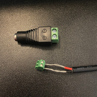
Figure 1_wire cutting Figure_2 wire in power jack Figure 3_circuit with LED
There are two types of power jack. One has two wires that I needed to stripe the rubber myself and insert it to the screw terminal (picture 1 and 2 above). The other one (picture 2) is simpler, and all you need to do is to insert and screw the wire into the jack. I set up the breadboard as picture 3.
Since I don't have the power supply, I used the Arduino Nano to set up my breadboard. I failed the first time (see Figure 4 and 5). I started to wonder what's the best way to troubleshoot when things don't work. Do I take everything off the breadboard at once and start over, or do I change one thing at a time? Since the code is correct, I assume that it's the wiring's problem.


Figure 5
Figure 4
I took every part out of the breadboard and started over. I tried to troubleshoot through researching on google and watching tutorials from the class website. After nothing worked, I asked on Discord. I tried a few things, but what worked was that I moved and giggled around the wires and changed to pin 13 (see setup 2). I'm still not sure what made the difference. Because I changed a few things at the same time, it's hard to determine what caused the failure in the first setup.
Working meter!
It's important to make sure your meter is working, so you could test if it's the components' problem when the setup doesn't have output. As I'm testing the meter, I also learned the symbols on the meter, like continuity is the diode/sound symbol. I could also measure a resister. I turned the meter to the setting marked with the Greek letter Omega. It turned out to be 0.2 Ohm. I tried to measure the volts of the LED without switching the meter to Volts, which the result of it is 0. I got confused with which the meter setting is to measure which part.
Measuring Voltage
I actually found a battery and battery clip, so I made a circuit with a 5V regulator. The battery is 9V, and the output from the regulator is about 5V.

Figure 6
A Switched LED Circuit
Then, I made a switched circuit with two LEDs (see Figure 7). I used green and red LEDs, and they have a different voltage drop. I pushed the switch while I measured the voltage. It was hard to do with only two hands. Then I added a third LED light (see Figure 8), which didn't light up. The first one is the brightest, and the second one is darker. It happened because each light needs 2V, so there will be no more voltage when it gets to the last one. When I tried to measure the amperage for one of the three LEDs. I couldn't get any value. I will definitely have to loop back and figure that problem out.


Figure 7 Figure 8
Then, I changed the switch to potentiometer. As I turn it from one end to another, the voltage got higher as the LED gets brighter, which means the voltage goes up as well (see video 1).
Video 1
I added two more switched to control the LED. As seen on Figure 9, I could turn any one of the three switches to turn on the light. If I make a single flow circuit with all three switches connected to each other (see Figure 10), I'd have to press all three buttons to turn on the LED.


Figure 9 Figure 10


Comments